Monday, September 23, 2013

Debugging Problems with the Linux sunxi rtl8188eu Wireless Driver

New: Updates are at the bottom!

I have a problem with rtl8188eu wireless driver.  I develop the OS for the MICILE tablet system and sometimes the wireless modules fail to initialize on boot or reboot.  Needless to say, this makes for unhappy customers.  This posting is a preliminary analysis of the problem with a possible path to a solution

What do I currently know of the problem?
  • Seems to happen when a lot of wifi networks are present
  • When it happens, the entire USB bus that the module is on fails to appear when lsusb is called
  • The rtl8188eu kernel module can not be unloaded, so only one chance to debug per reboot

WIFI Failed to Initialize!

So how can I solve such a problem?

Some items that need to be done before a solution can be found are:

1.  Replicate the problem reliably
2.  Need to sniff the USB power lines and the data packets
3.  Fix the rtl8188eu driver so it can be unloaded

To solve #1, I plan on finding every old wireless router I can and hook them all up in the same room to replicate an apartment with wifi on all sides.  I think 9 routers should do it, as that should form a grid of nine networks representing an apartment surrounded by wifi routers on all sides.  In addition, some kind of automated reboot loop will have to be written to power cycle the tablet until the problem occurs.  The problem only occurs 5 to to percent of the time, so some automated way must be found to make the problem happen.

Crowded Apartment WIFI Configuration


To solve #2, the tablet will be opened up, wires will be soldered to the onboard usb wifi module and a logic analyzer will monitor the usb bus and an oscilloscope will monitor the voltage rail.  Since the usb voltage is software controlled, it could be a bug in the way the power is brought up from a standby state.

USB Debug Points


To solve #3, I don't really care about the functionality of the driver because once the module comes up it works just fine.  I just need enough functionality in the driver to bring up the usb bus and the module and then fix the driver enough to be able to unload cleanly.  To that end, everything in between those two steps will be deleted from the module.

Wish me luck that the answer comes easily!

Day 2 Update!

Wires have been soldered to the USB pins.

USB Debug Wires
And interesting information has been found!  It was as I suspected!  When rebooting the tablet, the USB bus that the WIFI adapter is attached to does not power cycle correctly.

I instrumented the kernel with printk statements that clearly show the power to the USB bus should be turned off for several seconds during the boot sequence, but that is clearly not happening as shown by the logic analyzer hooked up to the USB power line.  On a cold boot however, it takes several seconds for the USB power line to come up, so that gives hope that it is in fact controlled by the AXP power controller and can be toggled.  My thinking is that if the power is turned off the USB correctly during a reboot sequence then the USB WIFI module will reset and come back properly every time.  Without the power cycle, the USB WIFI module can be left in a bad state between reboots and then fail to enumerate itself on the USB bus on a reboot.

From looking at the reference design schematics, it looks like the USB WIFI power should be hooked up to the LDO3 of the AXP209 power controller.  Let's hope the factory didn't deviate from the reference schematic.

USB WIFI Power Schematic

After some careful probing with a multimeter I can confirm that the power rail of the USB WIFI module is indeed connected to pin 41 (LDO3) of the AXP209 power controller chip.


I think we are almost there!  Now we just need to figure out how to turn on and off the LDO3 output of the AXP209 from the kernel.  Most likely at this point it will turn out to be a wrong setting in the script.bin configuration file for the tablet and need no code changes to the kernel or kernel drivers.  The datasheet for the AXP209 is in chinese, so this should be fun trying to figure out the proper I2C commands to turn the LDO3 output on and off.  The worst part is I just desoldered the very fine wires to the 0603 resistors used for spying on the I2C bus.  I'm not going to push my luck and try to reattach them so I will see if we can live without seeing what is happening on the bus.

More to come later!


Sunday, June 16, 2013

MAME on MICILE (Part 1)


Overview
This is the first part of a multi part series on running the MAME (Multiple Arcade Machine Emulator) on the MICILE development system.
  • Part 1 will show how to play a simple MAME game (this article you are reading)
  • Part 2 will show how to write a front end to pick different MAME games (coming soon)
  • Part 3 will show how to construct a little arcade cabinet to hold the tablet in viewable position so you can play all day long. (coming soon)
This not intended to be an exhaustive guide, there is lots of information about AdvanceMAME and Linux on the internet, so if you have more in depth questions, there is a wealth of information on the internet on how to fully use a MAME emulator on a Linux system.
Parts Needed
  • MICILE development system
    The MICILE development system consists of hardware and software that allows a linux based operating system to run on Allwinner A13 tablets. It also allows the easy development of python applications that run on the tablet. www.micile.com

    Note: You must be running a MICILE Operating System build of at least Beta1 RC3 E6 for these instructions to work.

    You must be running a MICILE Operating System build of at least "Beta1 RC1 E1". This first batch of pre-release MICILE development system tablets shipped with "Beta1 RC1". See the MICILE web site for how to check your operating system version and how to upgrade to the latest version of the operating system.
  • MAME (Multiple Arcade Machine Emulator
    MAME is an open source program which allows the emulation of arcade video games on a variety of hardware. It is so versatile that it has been successfully ported to run on everything from regular PC computers, smart phones, and even on a digital camera. MAME needs the ROMS for games in order to play them. A ROM is a dump of the software for the arcade game. http://advancemame.sourceforge.net/

    You will also need ROM dumps from video game circuit boards that you own.  After purchasing a video game circuit board, you can get ROM dumps from places like www.romnation.net for games that you own the circuit boards of.
  • Cheap chinese game pad off of eBay
    These are cheap generic gamepads sold on ebay that use the DragonRise chipset. I like cheap things. I got mine from this vendor on ebay. www.ebay.com
Assemble the hardware
  • Turn off the MICILE tablet if it is on by holding down the power button for 10 seconds and then releasing
  • Plug the gamepad into the tablet using the tablet's micro USB to USB Host adapter cable.
  • Turn on the tablet by holding the power button down for 5 seconds and then releasing. If needed, configure the MICILE tablet's wifi.
  • Wait for the tablet to finish booting. When the tablet has completed booting it will show its IP address on the screen.
  • Activate analog mode on the gamepad by pressing the ANALOG button on the joystick. The analog LED will be lit when the gamepad is in analog mode.
Installing MAME
  • MAME comes preinstalled on the MICILE tablet. I bet you thought this step would be a lot harder, didn't you?
Adding ROMs to MAME
  • When the MICILE tablet boots, it will show you its IP address, as shown in the last picture of the Assemble the Hardware section. We will use that IP address to access the MICILE tablet. The MICILE tablet shares a folder on the network which the MAME ROMs for games should be placed in.
  • To access the share folder, start by clicking on the Windows Icon on your taskbar.
  • That will bring up the start menu. Type in two backslashes followed by the IP address of the tablet. The backslash key is usually located above the space bar on the keyboard and is shared with the question mark.
  • A network window should appear showing the directories that the MICILE tablet is sharing on the network.
  • Double click on the folder mame_roms. A login window should appear the first time. Login using the the username of root and a password of password
  • Now drag and drop in your MAME ROMS. In my case, since I own an original Street Fighter II Circuit Board from a vintage standup arcade game of Street Fighter II and I feel like playing Street Figher II, I will be installing the ROM for Street Fighter II in this example.
  • Here is a shot of my vintage Street Fighter II circuit board. It is amazing how much they were able to do with such little computing power 20 years ago. Look at the size of those chips!
Launch MAME
  • Since we don't have a front end for MAME yet, we will need to launch MAME from a shell terminal. This will require a PC with a web browser running chrome. Type in the IP address of the MICILE tablet into the chrome browser and the MICILE web based IDE (Integrated Development Environment) will launch.
  • Click on the button labeled "Open Terminal". If this is the first time you have ever launched the shell, it will take up to 10 minutes for the tablet to generate its ssh encryption keys. Other times it may take up to a minute for the shell. Be patient, or use your favorite ssh client if you know how to use ssh already.
  • Eventually, the shell will ask you for a MICILE login otherwise known as a username. The default username is root. The default password for root user is password. When you type in the password nothing will appear on the screen as you are typing. This is expected. Just go ahead and type the password and press enter when the shell asks for the password.
  • Following my example earlier of adding the Street Fighter II ROM named sf2, we will launch Street Fighter 2 by typing the following command into the shell:
    run_advmame sf2

    The screen show below is out of date, please use the correct updated command of run_advmame instead of advmame!
  • A few seconds later, the load screen of the game will appear. Read the load screen and follow it's instructions.
  • Once past the load screens and the game is running, use the SELECT button on the gamepad to add a coin. Use the START button to start the game after adding the coin.
  • So this is the game in action
What's Next?
  • It's not too cool to have to lug around a laptop every time we want to play an arcade game. In Part 2 we will write a front end for MAME that runs on the MICILE tablet everytime the tablet boots and will allow us to choose a game using the touchscreen so the system becomes self contained. I've also got some cheapy wireless gamepads I picked up off ebay that I want to try.

Sunday, October 28, 2012

Fixing the Linux Camera Driver on an AllWinner A13 Tablet (Part 2)

This is a continuation of Part 1 Now we solder some very fine wires to the ends of the 0402 resistors on the camera's I2C bus. You can see an american penny in the image for scale.
Now we can use a multimeter to probe the pins on the A13 to find out which pins the camera's I2C bus are connected to.
Interesting... Probing has not gone as expected and the two locations which I thought were I2C lines do not seem to be directly connected to the pins on the A13 CPU. OK, time to do some systematic checking of the pins. From the configuration file for the tablet, it looks like the following pins should be connected
Pixel Clock  - E00 (114) *
Clock        - E01 (115) *
HSYNC        - E02 (116)
VSYNC        - E03 (117)
D0           - E04 (118) *
D1           - E05 (119) *
D2           - E06 (120) *
D3           - E07 (121) *
D4           - E08 (122) *
D5           - E09 (123) *
D6           - E10 (124) *
D7           - E11 (125) *
RESET        - Power3 (No idea what this means)
POWER_ENABLE - NC
STANDBY      - B10 (10)
As best as I can figure out after probing with a multimeter for two hours, the pins from the camera connector (pin 1 nearest the edge of the pcb) are connected to the following:
#1  - NC      
#2  - POWER    
#3  - [160] PB18 / TWI2_SDA  (I2C Data)
#4  - No Idea 
#5  - [161] PB17 / TWI2_SCK  (I2C Clock)
#6  - No Idea, but has a pullup resistor
#7  - No Idea
#8  - [01] PB10 (Standby)
#9  - No Idea
#10 - (Filter Capacitor)
#11 - (Filter Capacitor)
#12 - [125] D7
#13 - [114] PIXEL CLOCK
#14 - [124] D6
#15 - No Idea
#16 - [123] D5
#17 - [115] CLOCK
#18 - [122] D4
#19 - [118] D0
#20 - [121] D3
#21 - [119] D1
#22 - [120] D2
#23 - GND
#24 - GND
Which means I have soldered wires to the wrong place. It looks like the I2C pullup resistors are actually located very close the the CPU. It's going to be a tight squeeze, but what can you do. Here is a shot of the correct placement of the I2C debug wires on the pullup resistors next to the CPU.
On a side note, I think my tablet may have counterfeit memory chips (not really surprised). I had electrical tape over the memory chips to hold down some wires and when I removed the tape, the markings came off the chips and stuck to the electrical tape.

DISASTER! I seem to have broken something. I suspect when I pulled the tape off the DDR RAM, it broke a solder joint underneath the chip. All I get now is
HELLO! BOOT0 is starting!
boot0 version : 1.3.0
initializing SDRAM Fail.
I think my only choice is to attempt to reflow the memory chip with a heat gun. That's it for now. Check in for Part 3 if I can get it working again.

Thursday, October 25, 2012

Fixing the Linux Camera Driver on an AllWinner A13 Tablet (Part 1)

I've been working on getting Linux to be fully functional on an AllWinner A13 tablet. If you haven't heard, AllWinner A10 and A13 CPUs are the greatest thing since sliced bread when it comes to working with cheap hardware. A13 tablets go for $39 wholesale in China, and about $65 shipped to your door in the USA. The open source driver for the A13 camera doesn't seem to work, so I will be trying to find out what the problem is and fix it. The plan is to tap the I2C bus that controls the camera and spy on it with a logic analyzer to see what is going wrong with the driver. This post will just cover figuring out which lines to tap into, and a follow up post will show the actual analysis of the I2C bus. This is a technique I have used successfully to fix the driver for the Goodix GT811 touchscreen.

Generic A13 Tablet
The camera is that little round cutout at the bottom of the tablet shown above. A closeup of the camera can be seen below.
Closeup of the Camera
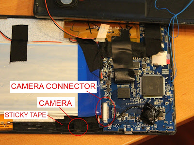
Amazingly, this camera is held in place by a piece of sticky tape. Yes, sticky tape. Chinese manufacturing at its finest. But it seems to stay in place, so who am I to criticize? First step is to crack open the tablet. These tablets are snap together, so no screws hold the two halves of the tablet together. Below is a picture of the tablet after it has been opened up. The LCD screen is facing down against the table top, and the PCB and battery are mounted to the back of the LCD. The back of the plastic cover can be seen in the top of the picture. I have a lot of debug wires (the blue wires running everywhere) which are attached to the back plastic cover. Not all the sticky tape is from the factory, some is mine because the factory tape loses its grip after repeated removals.
A13 Tablet Guts
Unrelated anecdote (your reading my blog so you have to listen to my ramblings too), many years ago when I was shopping for electronics in shadier parts of Hong Kong, every hawker selling questionable electronics would always claim that even though the brand was something that nobody had ever heard of, they all had "Sony guts" In the picture above, you can see how the camera at the bottom is just held in place with sticky tape. I didn't remove all the tape holding the camera in place because I was worried it would never go back in place again. You can also see the camera connector that I am interested in. Below is a closeup of the camera connector
Close up of the Camera Connector
So from the A13 datasheet, we know the CSI has the following signal lines:

CSI_PCLK - Pixel Clock
CSI_MCLK - Sensor Clock
CSI_HSYNC - Horizontal Sync
CSI_VSYNC - Vertical Sync
CSI_D7:0 - 8 Data lines

We also know that the tablet uses a GalaxyCore GC0308 Camera. From the GC0308 datasheet we see that it uses the following signal lines

AVDD25 - 0.1uF Filtering cap to ground
VREF - 0.1uF Filtering cap to ground
SBDA - I2C Data Line
SBCL - I2C Clock Line
D7:0 - 8 Data Lines
GND - Ground
PWDN - Powerdown signal (active high)
HSYNC - HSYNC output
VSYNC - VSYNC output
DVDD28 - 2.8V input
RESETB - Reset (active low)
INCLK - Input Clock

The 8 data lines are easy to spot with the 4 element resistor arrays protecting the data bus.

The 2 filtering caps for AVDD25 and VREF are also easy to spot.

That just leaves the 2 mystery resistors. It is easy to tell if they are the pullups required for the I2C bus by checking if the side of the resistor not connected to the flex connector are tied together and tied to 3.3V. Then we know for sure they are the pullups for the I2C data and clock lines and we can tap into the I2C signals by soldering some very fine wires to the side of the resistor that is connected to the flex connector.

After checking the voltage at the two resistors, it is confirmed that they are both at 2.8V which means they are indeed the I2C pullup resistors. (I said 3.3V, close enough)

In Part 2, I will solder fine wires to the resistors and we hook the logic analyzer up! Always fun soldering wires to 0402 resistors (Thats 0.04" x 0.02", or about the width of 2 human hairs side by side)

Sunday, July 8, 2012

Enabling Composite Video on the Mele A1000 Set Top Box (AllWinner A10)

Just a quick program to enable the composite video interface on the Mele A1000 Set Top Box.
 /***  
  * Small program to enable composite video (NTSC) on Mele A1000  
  *  
  * Based on information from   
  * http://www.cnx-software.com/2012/04/28/how-to-create-your-own-debian-ubuntu-image-for-mele-a1000-allwinner-a10-based-stb/  
  * which shows how to enable the VGA interface  
  *  
  * Copyright (C) 2012 Lawrence Yu  
  *  
  * Permission is hereby granted, free of charge, to any person obtaining a copy of this software and associated   
  * documentation files (the "Software"), to deal in the Software without restriction, including without limitation   
  * the rights to use, copy, modify, merge, publish, distribute, sublicense, and/or sell copies of the Software,   
  * and to permit persons to whom the Software is furnished to do so, subject to the following conditions:  
  *  
  * The above copyright notice and this permission notice shall be included in all copies or substantial portions of   
  * the Software.  
  *  
  * THE SOFTWARE IS PROVIDED "AS IS", WITHOUT WARRANTY OF ANY KIND, EXPRESS OR IMPLIED, INCLUDING BUT NOT LIMITED TO   
  * THE WARRANTIES OF MERCHANTABILITY, FITNESS FOR A PARTICULAR PURPOSE AND NONINFRINGEMENT. IN NO EVENT SHALL THE   
  * AUTHORS OR COPYRIGHT HOLDERS BE LIABLE FOR ANY CLAIM, DAMAGES OR OTHER LIABILITY, WHETHER IN AN ACTION OF CONTRACT,   
  * TORT OR OTHERWISE, ARISING FROM, OUT OF OR IN CONNECTION WITH THE SOFTWARE OR THE USE OR OTHER DEALINGS IN THE   
  * SOFTWARE.  
 ***/   
   
 // --------------------------------------------------  
 // Includes  
 // --------------------------------------------------  
   #include <stdio.h>  
   #include <fcntl.h>  
   
 // --------------------------------------------------  
 // Constants  
 // --------------------------------------------------  
   #define DISP_CMD_TV_ON       0x180  
   #define DISP_CMD_TV_OFF      0x181  
   #define DISP_CMD_TV_SET_MODE    0x182  
   #define DISP_CMD_HDMI_OFF     0x1c1  
     
   #define NOARG 0x00  
   
 // --------------------------------------------------  
 // Global Variables  
 // --------------------------------------------------  
   int g_display;  
   
 // --------------------------------------------------  
 // Functions  
 // --------------------------------------------------  
   void cmd(unsigned long cmd, unsigned long argval) {  
     // Variables  
       unsigned long args[4];  
       int      ret;  
         
     // Send the command  
       args[0] = 0x00;  
       args[1] = argval;  
       args[2] = 0x00;  
       args[3] = 0x00;  
       ret = ioctl(g_display, cmd, (unsigned long)args);  
       printf("Sent Command %02X(%02X) = %02X\n", cmd, argval, ret);  
   }      
   
 // --------------------------------------------------  
 // Main Functions  
 // --------------------------------------------------  
   int main(int argc, char const *argv[]) {  
     // Initialize the display  
       g_display = open("/dev/disp", O_RDWR, 0);  
   
     // Turn off the HDMI  
       cmd(DISP_CMD_HDMI_OFF, NOARG);  
   
     // Turn off the TV  
       cmd(DISP_CMD_TV_OFF, NOARG);  
     
       // Set the TV Mode  
       cmd(DISP_CMD_TV_SET_MODE, 0x0e);  
   
     // Turn on the TV  
       cmd(DISP_CMD_TV_ON, NOARG);  
   }  

Friday, March 9, 2012

Better Remote Desktop Resolutions on Linux

Did you know you can remote desktop into a linux machine and have the remote desktop resolution be much larger than the physical screen attached to the actual linux machine? I have a linux machine with an old 14" LCD that could only go up to 1024x768. My main development machine has 1600x1200 monitors. I found it was possible to have the remote desktop session be at the full 1600x1200 even though the monitor connected to the linux machine could only go up to 1024x768.

Simply use the following command:

xrandr --output VGA-0 --panning 1600x1200
Now your remote desktop session will be displayed as if it were on a 1600x1200 monitor. Development bliss...

If you primary monitor is not "VGA-0", replace "VGA-0" with your monitor. To find out the names of your monitors, just run xrandr without any parameters
xrandr

Monday, January 2, 2012

Creating a Production Rails 3.1 Server (Ubuntu 10.04 LTS)

The following are instructions on how to create a production Rails 3.1 Server using Ubuntu 10.04 LTS

Download the Ubuntu 10.04.3 LTS 64 bit Server ISO from here and install it. Install the "LAMP Server" and "OpenSSH Server" packages when prompted.
Install prerequisites
sudo apt-get install build-essential libyaml-dev zlib1g-dev libcurl4-openssl-dev libssl-dev libopenssl-ruby apache2-prefork-dev libapr1-dev libaprutil1-dev
Download the Ruby source code and compile it
cd ~
mkdir ruby_src
cd ruby_src
wget http://ftp.ruby-lang.org/pub/ruby/1.9/ruby-1.9.3-p0.tar.gz
tar -zxvf ruby-1.9.3-p0.tar.gz
cd ruby-1.9.3-p0
./configure
make
sudo make install
Verify Ruby installed correctly
ruby -v
Expected output is "ruby 1.9.3p0 (2011-10-30 revision 33570) [x86_64-linux]"
Download the RubyGems source code and compile it
cd ~
mkdir rubygems_src
cd rubygems_src
wget http://rubyforge.org/frs/download.php/75573/rubygems-1.8.12.tgz
tar -zxvf rubygems-1.8.12.tgz
cd rubygems-1.8.12
sudo ruby setup.rb
Verify RubyGems installed correctly
gem -v
Expected output is "1.8.12"
Install Rails
sudo gem install rails
Verify Rails installed correctly
rails -v
Expected output is "Rails 3.1.3"
Install Phusion Passenger
sudo gem install passenger
sudo passenger-install-apache2-module
Configure Apache by adding these lines to /etc/apache2/apache2.conf
LoadModule passenger_module /usr/local/lib/ruby/gems/1.9.1/gems/passenger-3.0.11/ext/apache2/mod_passenger.so
PassengerRoot /usr/local/lib/ruby/gems/1.9.1/gems/passenger-3.0.11
PassengerRuby /usr/local/bin/ruby
Configure your rails application by adding these lines to /etc/apache2/apache2.conf, assuming the name of your app is Mytest. Make sure to change the ServerName to the name of the server.
      <VirtualHost *:80>
        ServerName www.yourhost.com
        DocumentRoot /usr/local/mytest/public
        <Directory /usr/local/mytest/public>
           AllowOverride all
           Options -MultiViews
        </Directory>
      </VirtualHost>
    
Restart Apache
sudo /etc/init.d/apache2 restart
Modify the Gemfile to include execjs and therubyracer if needed. Then run "sudo bundle install"
Rails application housekeeping
sudo bundle update
RAILS_ENV=production rake db:create db:schema:load
rake assets:precompile
sudo /etc/init.d/apache2 restart